SCT2450KEGC11
ActiveRohm Semiconductor
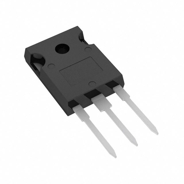
SILICON CARBIDE MOSFET, SINGLE, N CHANNEL, 10 A, 1.2 KV, 0.45 OHM, TO-247N
Deep-Dive with AI
Search across all available documentation for this part.
SCT2450KEGC11
ActiveRohm Semiconductor
SILICON CARBIDE MOSFET, SINGLE, N CHANNEL, 10 A, 1.2 KV, 0.45 OHM, TO-247N
Technical Specifications
Parameters and characteristics for this part
| Specification | SCT2450KEGC11 |
|---|---|
| Current - Continuous Drain (Id) @ 25°C | 10 A |
| Drain to Source Voltage (Vdss) | 1200 V |
| Drive Voltage (Max Rds On, Min Rds On) | 18 V |
| FET Type | N-Channel |
| Gate Charge (Qg) (Max) @ Vgs | 27 nC |
| Input Capacitance (Ciss) (Max) @ Vds | 463 pF |
| Mounting Type | Through Hole |
| Operating Temperature | 175 °C |
| Package / Case | TO-247-3 |
| Power Dissipation (Max) [Max] | 85 W |
| Rds On (Max) @ Id, Vgs | 585 mOhm |
| Supplier Device Package | TO-247N |
| Vgs (Max) [Max] | 22 V |
| Vgs (Max) [Min] | -6 V |
Pricing
Prices provided here are for design reference only. For realtime values and availability, please visit the distributors directly
Description
General part information
SCT2450KEHR Series
This is SiC (Silicon Carbide) planar MOSFET. This product have high voltage resistance, low ON resistance, and fast switching speed features. AEC-Q101 qualified automotive grade product.
Documents
Technical documentation and resources