UFZVFHTE-1730B
ActiveRohm Semiconductor
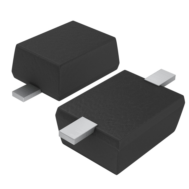
500MW 30V, SOD-323FL, SMALL AND HIGH POWER ZENER DIODE FOR AUTOMOTIVE
Deep-Dive with AI
Search across all available documentation for this part.
UFZVFHTE-1730B
ActiveRohm Semiconductor
500MW 30V, SOD-323FL, SMALL AND HIGH POWER ZENER DIODE FOR AUTOMOTIVE
Deep-Dive with AI
Technical Specifications
Parameters and characteristics for this part
| Specification | UFZVFHTE-1730B |
|---|---|
| Current - Reverse Leakage @ Vr | 200 nA |
| Grade | Automotive |
| Impedance (Max) (Zzt) [Max] | 55 Ohms |
| Mounting Type | Surface Mount |
| Operating Temperature | 150 °C |
| Package / Case | SOD-323F, SC-90 |
| Power - Max [Max] | 500 mW |
| Qualification | AEC-Q101 |
| Supplier Device Package | UMD2 |
| Tolerance | 2.53 % |
| Voltage - Zener (Nom) (Vz) | 30 V |
Pricing
Prices provided here are for design reference only. For realtime values and availability, please visit the distributors directly
| Distributor | Package | Quantity | $ | |
|---|---|---|---|---|
| Digikey | Cut Tape (CT) | 1 | $ 0.31 | |
| 10 | $ 0.21 | |||
| 100 | $ 0.10 | |||
| 500 | $ 0.09 | |||
| 1000 | $ 0.06 | |||
| Digi-Reel® | 1 | $ 0.31 | ||
| 10 | $ 0.21 | |||
| 100 | $ 0.10 | |||
| 500 | $ 0.09 | |||
| 1000 | $ 0.06 | |||
| Tape & Reel (TR) | 3000 | $ 0.04 | ||
| 6000 | $ 0.03 | |||
| 9000 | $ 0.03 | |||
| Newark | Each (Supplied on Cut Tape) | 1 | $ 0.24 | |
| 10 | $ 0.16 | |||
| 25 | $ 0.13 | |||
| 50 | $ 0.11 | |||
| 100 | $ 0.08 | |||
| 250 | $ 0.08 | |||
| 500 | $ 0.07 | |||
| 1000 | $ 0.07 | |||
Description
General part information
UFZVFH5.1B Series
UFZVFH5.6B is a Zener Diode with 500mW power dissipation, suitable for voltage regulation. It is a highly reliable product for automotive.
Documents
Technical documentation and resources