UCC21520ADWR
Active5.7KVRMS 4A/6A DUAL-CHANNEL ISOLATED GATE DRIVER WITH DUAL INPUT AND DISABLE PIN IN DW PACKAGE
Deep-Dive with AI
Search across all available documentation for this part.
UCC21520ADWR
Active5.7KVRMS 4A/6A DUAL-CHANNEL ISOLATED GATE DRIVER WITH DUAL INPUT AND DISABLE PIN IN DW PACKAGE
Deep-Dive with AI
Technical Specifications
Parameters and characteristics for this part
| Specification | UCC21520ADWR |
|---|---|
| Approval Agency | CQC, CSA, VDE, UR |
| Common Mode Transient Immunity (Min) [Min] | 100 V/ns |
| Current - Output High, Low | 4 A, 6 A |
| Mounting Type | Surface Mount |
| Number of Channels [custom] | 2 |
| Operating Temperature [Max] | 125 °C |
| Operating Temperature [Min] | -40 °C |
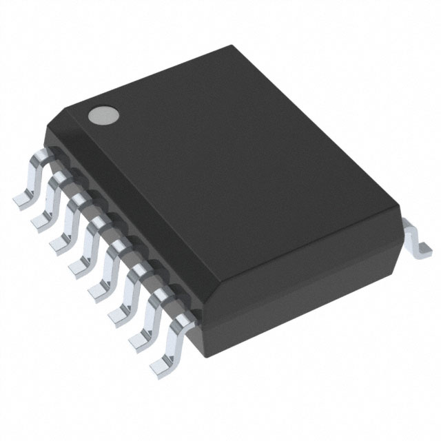
| Package / Case | 16-SOIC |
| Package / Case [x] | 0.295 in |
| Package / Case [y] | 7.5 mm |
| Propagation Delay tpLH / tpHL (Max) [Max] | 30 ns |
| Pulse Width Distortion (Max) [Max] | 6 ns |
| Rise / Fall Time (Typ) [custom] | 7 ns |
| Rise / Fall Time (Typ) [custom] | 6 ns |
| Supplier Device Package | 16-SOIC |
| Technology | Capacitive Coupling |
| Voltage - Isolation | 5700 Vrms |
| Voltage - Output Supply [Max] | 25 V |
| Voltage - Output Supply [Min] | 6.5 V |
Pricing
Prices provided here are for design reference only. For realtime values and availability, please visit the distributors directly
| Distributor | Package | Quantity | $ | |
|---|---|---|---|---|
| Digikey | Cut Tape (CT) | 1 | $ 4.36 | |
| 10 | $ 3.92 | |||
| 25 | $ 3.70 | |||
| 100 | $ 3.21 | |||
| 250 | $ 3.05 | |||
| 500 | $ 2.73 | |||
| 1000 | $ 2.30 | |||
| Digi-Reel® | 1 | $ 4.36 | ||
| 10 | $ 3.92 | |||
| 25 | $ 3.70 | |||
| 100 | $ 3.21 | |||
| 250 | $ 3.05 | |||
| 500 | $ 2.73 | |||
| 1000 | $ 2.30 | |||
| Tape & Reel (TR) | 2000 | $ 2.04 | ||
| Texas Instruments | LARGE T&R | 1 | $ 3.29 | |
| 100 | $ 2.88 | |||
| 250 | $ 2.02 | |||
| 1000 | $ 1.63 | |||
Description
General part information
UCC21520-Q1 Series
The UCC21520 is an isolated dual-channel gate driver with 4A source and 6A sink peak current. It is designed to drive power MOSFETs, IGBTs, and SiC MOSFETs up to 5MHz.
The input side is isolated from the two output drivers by a 5.7kVRMS reinforced isolation barrier, with a minimum of 125V/ns common-mode transient immunity (CMTI). Internal functional isolation between the two secondary-side drivers allows a working voltage of up to 1500VDC.
Every driver can be configured as two low-side drivers, two high-side drivers, or a half-bridge driver with programmable dead time (DT). A disable pin shuts down both outputs simultaneously when it is set high, and allows normal operation when left open or grounded. As a fail-safe measure, primary-side logic failures force both outputs low.
Documents
Technical documentation and resources