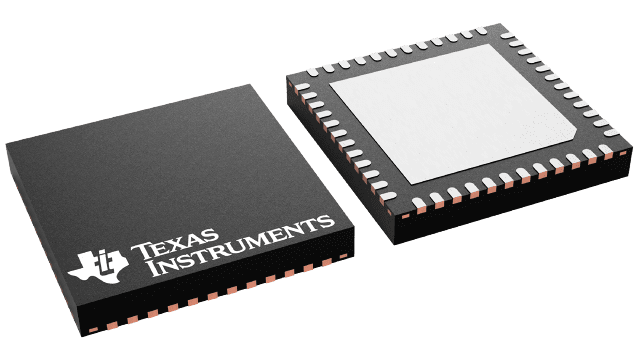
UCD9220RGZR
Active2MHZ, 2 RAIL, 4 PHASE DIGITAL PWM BUCK CONTROLLER
Deep-Dive with AI
Search across all available documentation for this part.

UCD9220RGZR
Active2MHZ, 2 RAIL, 4 PHASE DIGITAL PWM BUCK CONTROLLER
Deep-Dive with AI
Technical Specifications
Parameters and characteristics for this part
| Specification | UCD9220RGZR |
|---|---|
| Clock Sync | True |
| Control Features | Tracking |
| Duty Cycle (Max) [Max] | 100 % |
| Function | Step-Down |
| Mounting Type | Surface Mount |
| Number of Outputs | 4 |
| Operating Temperature [Max] | 125 ¯C |
| Operating Temperature [Min] | -40 °C |
| Output Configuration | Positive |
| Output Phases | 4 |
| Output Type | PWM Signal |
| Package / Case | 48-VFQFN Exposed Pad |
| Serial Interfaces | SMBus, I2C, PMBus |
| Supplier Device Package | 48-VQFN (7x7) |
| Synchronous Rectifier | False |
| Topology | Buck |
Pricing
Prices provided here are for design reference only. For realtime values and availability, please visit the distributors directly
| Distributor | Package | Quantity | $ | |
|---|---|---|---|---|
| Digikey | Cut Tape (CT) | 1 | $ 6.77 | |
| Digi-Reel® | 1 | $ 6.77 | ||
| Tape & Reel (TR) | 2500 | $ 3.70 | ||
| Texas Instruments | LARGE T&R | 1 | $ 5.96 | |
| 100 | $ 4.86 | |||
| 250 | $ 3.82 | |||
| 1000 | $ 3.24 | |||
Description
General part information
UCD9220 Series
The UCD9220 is a multi-rail, multi-phase synchronous buck digital PWM controller designed for non-isolated DC/DC power applications. This device integrates dedicated circuitry for DC/DC loop management with flash memory and a serial interface to support configuration, monitoring and management.
The UCD9220 was designed to provide a wide variety of desirable features for non-isolated DC/DC converter applications while minimizing the total system component count by reducing external circuits. The solution integrates multi-loop management with sequencing, margining, tracking and intelligent phase management to optimize for total system efficiency. Additionally, loop compensation and calibration are supported without the need to add external components.
To facilitate configuring the device, the Texas Instruments Fusion Digital Power™ Designer is provided. This PC based Graphical User Interface offers an intuitive interface to the device. This tool allows the design engineer to configure the system operating parameters for the application, store the configuration to on-chip non-volatile memory and observe both frequency domain and time domain simulations for each of the power stage outputs.
Documents
Technical documentation and resources


