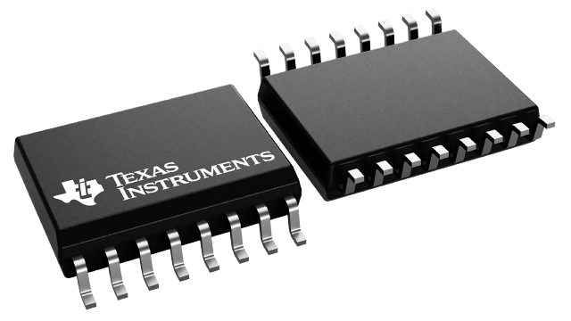
UC2861DW
ActiveRESONANT-MODE PWM WITH 16.5/10.5V UVLO, ALTERNATING OUTPUTS, AND FIXED OFF TIME, -25C TO 85C
Deep-Dive with AI
Search across all available documentation for this part.

UC2861DW
ActiveRESONANT-MODE PWM WITH 16.5/10.5V UVLO, ALTERNATING OUTPUTS, AND FIXED OFF TIME, -25C TO 85C
Deep-Dive with AI
Technical Specifications
Parameters and characteristics for this part
| Specification | UC2861DW |
|---|---|
| Control Features | Soft Start |
| Frequency - Switching [Max] | 1 MHz |
| Frequency - Switching [Min] | 10 kHz |
| Internal Switch(s) | True |
| Mounting Type | Surface Mount |
| Operating Temperature [Max] | 85 C |
| Operating Temperature [Min] | -25 °C |
| Output Isolation | Non-Isolated |
| Package / Case | 16-SOIC |
| Package / Case [x] | 0.295 in |
| Package / Case [y] | 7.5 mm |
| Supplier Device Package | 16-SOIC |
| Topology | Half-Bridge, Push-Pull, Full-Bridge |
| Voltage - Start Up | 16.5 V |
| Voltage - Supply (Vcc/Vdd) [Max] | 22 V |
| Voltage - Supply (Vcc/Vdd) [Min] | 10.5 V |
Pricing
Prices provided here are for design reference only. For realtime values and availability, please visit the distributors directly
| Distributor | Package | Quantity | $ | |
|---|---|---|---|---|
| Digikey | Bulk | 67 | $ 4.49 | |
| Tube | 200 | $ 5.10 | ||
| Texas Instruments | TUBE | 1 | $ 6.05 | |
| 100 | $ 4.93 | |||
| 250 | $ 3.88 | |||
| 1000 | $ 3.29 | |||
Description
General part information
UC2861 Series
The UC1861-1868 family of ICs is optimized for the control of Zero Current Switched and Zero Voltage Switched quasi-resonant converters. Differences between members of this device family result from the various combinations of UVLO thresholds and output options. Additionally, the one-shot pulse steering logic is configured to program either on-time for ZCS systems (UC1865-1868), or off-time for ZVS applications (UC1861-1864).
The primary control blocks implemented include an error amplifier to compensate the overall system loop and to drive a voltage controlled oscillator (VCO), featuring programmable minimum and maximum frequencies. Triggered by the VCO, the one-shot generates pulses of a programmed maximum width, which can be modulated by the Zero Detection comparator. This circuit facilitates "true" zero current or voltage switching over various line, load, and temperature changes, and is also able to accommodate the resonant components' initial tolerances.
Under-Voltage Lockout is incorporated to facilitate safe starts upon power-up. The supply current during the under-voltage lockout period is typically less than 150µA, and the outputs are actively forced to the low state.
Documents
Technical documentation and resources


