2SCR542PT100
ActiveRohm Semiconductor
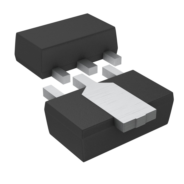
NPN, SOT-89, 30V 5A, DRIVER TRANSISTOR
Deep-Dive with AI
Search across all available documentation for this part.
2SCR542PT100
ActiveRohm Semiconductor
NPN, SOT-89, 30V 5A, DRIVER TRANSISTOR
Deep-Dive with AI
Technical Specifications
Parameters and characteristics for this part
| Specification | 2SCR542PT100 |
|---|---|
| Current - Collector (Ic) (Max) | 5 A |
| Current - Collector Cutoff (Max) [Max] | 1 µA |
| DC Current Gain (hFE) (Min) @ Ic, Vce [Min] | 200 |
| Frequency - Transition | 250 MHz |
| Mounting Type | Surface Mount |
| Operating Temperature | 150 °C |
| Package / Case | TO-243AA |
| Power - Max [Max] | 2 W |
| Transistor Type | NPN |
| Vce Saturation (Max) @ Ib, Ic | 400 mV |
| Voltage - Collector Emitter Breakdown (Max) [Max] | 30 V |
Pricing
Prices provided here are for design reference only. For realtime values and availability, please visit the distributors directly
| Distributor | Package | Quantity | $ | |
|---|---|---|---|---|
| Digikey | Cut Tape (CT) | 1 | $ 0.74 | |
| 10 | $ 0.64 | |||
| 100 | $ 0.44 | |||
| 500 | $ 0.37 | |||
| Digi-Reel® | 1 | $ 0.74 | ||
| 10 | $ 0.64 | |||
| 100 | $ 0.44 | |||
| 500 | $ 0.37 | |||
| Tape & Reel (TR) | 1000 | $ 0.32 | ||
| 2000 | $ 0.28 | |||
| 5000 | $ 0.27 | |||
| 10000 | $ 0.25 | |||
| 25000 | $ 0.24 | |||
| Newark | Each (Supplied on Cut Tape) | 1 | $ 1.12 | |
| 10 | $ 0.71 | |||
| 25 | $ 0.63 | |||
| 50 | $ 0.55 | |||
| 100 | $ 0.47 | |||
| 250 | $ 0.42 | |||
| 500 | $ 0.37 | |||
| 1000 | $ 0.34 | |||
Description
General part information
2SCR542PFRA Series
Various products are available in lineup developed focusing on energy-saving and high reliability as main concepts, covering from ultra-compact packages to power-packages to meet the needs in market.
Documents
Technical documentation and resources