2SAR564F3TR
ActiveRohm Semiconductor
SMALL AND EXCELLENT THERMAL CONDUCTIVITY, PNP -4A -80V MIDDLE POWER TRANSISTOR
Deep-Dive with AI
Search across all available documentation for this part.
2SAR564F3TR
ActiveRohm Semiconductor
SMALL AND EXCELLENT THERMAL CONDUCTIVITY, PNP -4A -80V MIDDLE POWER TRANSISTOR
Deep-Dive with AI
Technical Specifications
Parameters and characteristics for this part
| Specification | 2SAR564F3TR |
|---|---|
| Current - Collector (Ic) (Max) [Max] | 4 A |
| Current - Collector Cutoff (Max) [Max] | 1 µA |
| DC Current Gain (hFE) (Min) @ Ic, Vce [Min] | 120 |
| Mounting Type | Surface Mount |
| Operating Temperature | 150 °C |
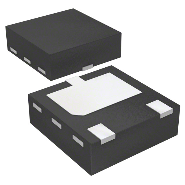
| Package / Case | 3-UDFN Exposed Pad |
| Power - Max [Max] | 1 W |
| Supplier Device Package | HUML2020L3 |
| Transistor Type | PNP |
| Vce Saturation (Max) @ Ib, Ic | 360 mV |
| Voltage - Collector Emitter Breakdown (Max) [Max] | 80 V |
Pricing
Prices provided here are for design reference only. For realtime values and availability, please visit the distributors directly
Description
General part information
2SAR564F3 Series
2SAR564F3 is a middle power transistor with Low VCE(sat), suitable for low frequency amplifier. HUML2020L3 (DFN2020-3S) is a small leadless surface mount package with excellent thermal and electrical conductivity.
Documents
Technical documentation and resources