RUF025N02FRATL
ActiveRohm Semiconductor
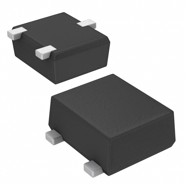
MOSFET, AEC-Q101, N-CH, 20V, TUMT
Deep-Dive with AI
Search across all available documentation for this part.
RUF025N02FRATL
ActiveRohm Semiconductor
MOSFET, AEC-Q101, N-CH, 20V, TUMT
Deep-Dive with AI
Technical Specifications
Parameters and characteristics for this part
| Specification | RUF025N02FRATL |
|---|---|
| Current - Continuous Drain (Id) @ 25°C | 2.5 A |
| Drain to Source Voltage (Vdss) | 20 V |
| Drive Voltage (Max Rds On, Min Rds On) | 4.5 V, 1.5 V |
| FET Type | N-Channel |
| Gate Charge (Qg) (Max) @ Vgs | 5 nC |
| Grade | Automotive |
| Input Capacitance (Ciss) (Max) @ Vds | 370 pF |
| Mounting Type | Surface Mount |
| Operating Temperature | 150 °C |
| Qualification | AEC-Q101 |
| Rds On (Max) @ Id, Vgs | 54 mOhm |
| Supplier Device Package | TUMT3 |
| Technology | MOSFET (Metal Oxide) |
| Vgs (Max) | 10 V |
| Vgs(th) (Max) @ Id | 1.3 V |
Pricing
Prices provided here are for design reference only. For realtime values and availability, please visit the distributors directly
Description
General part information
RUF025N02FRA Series
RUF025N02FRA is the high reliability Automotive MOSFET, suitable for the switching application.
Documents
Technical documentation and resources