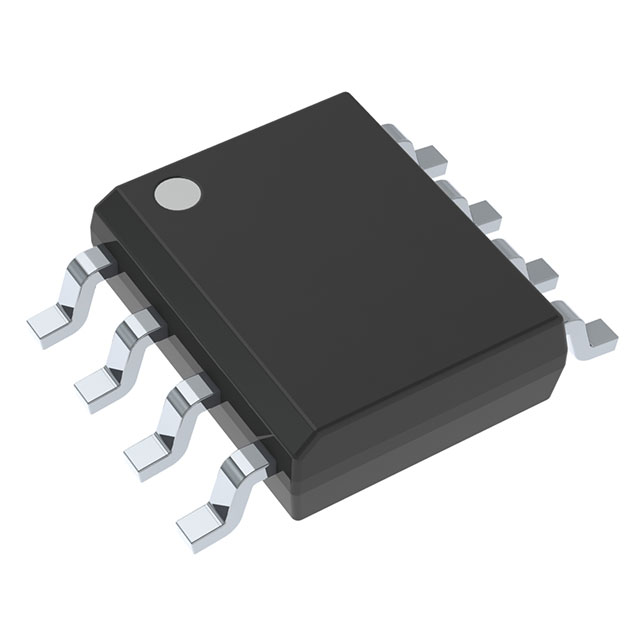
UC3902D
Active20V LOAD SHARE CONTROLLER, 0°C TO 70°C
Deep-Dive with AI
Search across all available documentation for this part.

UC3902D
Active20V LOAD SHARE CONTROLLER, 0°C TO 70°C
Technical Specifications
Parameters and characteristics for this part
| Specification | UC3902D |
|---|---|
| Applications | Load Share Controller |
| Current - Supply | 4 mA |
| Mounting Type | Surface Mount |
| Operating Temperature [Max] | 100 °C |
| Operating Temperature [Min] | -40 °C |
| Package / Case | 8-SOIC |
| Package / Case [x] | 0.154 in |
| Package / Case [y] | 3.9 mm |
| Supplier Device Package | 8-SOIC |
| Voltage - Supply [Max] | 20 V |
| Voltage - Supply [Min] | 2.7 V |
Pricing
Prices provided here are for design reference only. For realtime values and availability, please visit the distributors directly
| Distributor | Package | Quantity | $ | |
|---|---|---|---|---|
| Digikey | Tube | 1 | $ 5.49 | |
| 10 | $ 4.93 | |||
| 75 | $ 4.66 | |||
| 150 | $ 4.04 | |||
| 300 | $ 3.83 | |||
| 525 | $ 3.44 | |||
| 1050 | $ 2.90 | |||
| 2550 | $ 2.76 | |||
| Texas Instruments | TUBE | 1 | $ 4.77 | |
| 100 | $ 4.18 | |||
| 250 | $ 2.93 | |||
| 1000 | $ 2.36 | |||
Description
General part information
UC3902 Series
The UC3902 load share controller is an 8-pin device that balances the current drawn from independent, paralleled power supplies. Load sharing is accomplished by adjusting each supplies’ output current to a level proportional to the voltage on a share bus.
The master power supply, which is automatically designated as the supply that regulates to the highest voltage, drives the share bus with a voltage proportional to its output current. The UC3902 trims the output voltage of the other paralleled supplies so that they each support their share of the load current. Typically, each supply is designed for the same current level although that is not necessary for use with the UC3902. By appropriately scaling the current sense resistor, supplies with different output current capability can be paralleled with each supply providing the same percentage of their output current capability for a particular load.
A differential line is used for the share bus to maximize noise immunity and accommodate different voltage drops in each power converter’s ground return line. Trimming of each converter’s output voltage is accomplished by injecting a small current into the output voltage sense line, which requires a small resistance (typically 20 Ω to 100 Ω) to be inserted.


