Technical Specifications
Parameters and characteristics for this part
| Specification | VNH5180A-E |
|---|---|
| Current - Output | 8 A |
| Function | Driver - Fully Integrated, Control and Power Stage |
| Grade | Automotive |
| Interface | PWM, Parallel |
| Motor Type - AC, DC | Brushed DC |
| Mounting Type | Surface Mount |
| Operating Temperature [Max] | 150 °C |
| Operating Temperature [Min] | -40 °C |
| Output Configuration | Half Bridge (2) |
| Package / Case | 0.295 in |
| Package / Case | 36-PowerBFSOP |
| Package / Case [x] | 7.5 mm |
| Supplier Device Package | PowerSSO-36 TP |
| Technology | Power MOSFET |
| Voltage - Load [Max] | 18 V |
| Voltage - Load [Min] | 5.5 V |
| Voltage - Supply [Max] | 18 V |
| Voltage - Supply [Min] | 5.5 V |
Pricing
Prices provided here are for design reference only. For realtime values and availability, please visit the distributors directly
| Distributor | Package | Quantity | $ | |
|---|---|---|---|---|
| Digikey | Tube | 1 | $ 3.93 | |
| 10 | $ 3.53 | |||
| 49 | $ 3.34 | |||
| 147 | $ 2.89 | |||
| 294 | $ 2.74 | |||
| 539 | $ 2.46 | |||
| 1029 | $ 2.08 | |||
| 2548 | $ 1.97 | |||
| 5047 | $ 1.90 | |||
Description
General part information
VNH5180A-E Series
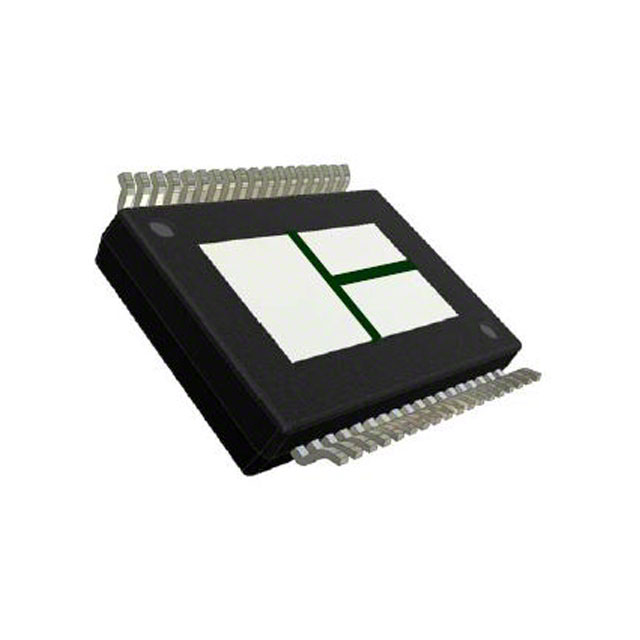
The VNH5180A-E is a full bridge motor driver intended for a wide range of automotive applications. The device incorporates a dual monolithic high-side driver and two low-side switches. Both switches are designed using STMicroelectronics’ well known and proven proprietary VIPower®M0 technology that allows to efficiently integrate on the same die a true Power MOSFET with an intelligent signal/protection circuitry. The three dies are assembled in PowerSSO-36 TP package on electrically isolated leadframes. This package, specifically designed for the harsh automotive environment offers improved thermal performance thanks to exposed die pads. Moreover, its fully symmetrical mechanical design allows superior manufacturability at board level. The input signals INAand INBcan directly interface to the microcontroller to select the motor direction and the brake condition. The DIAGA/ENAor DIAGB/ENB, when connected to an external pull-up resistor, enables one leg of the bridge. Each DIAGA/ENAprovides a feedback digital diagnostic signal as well. The normal operating condition is explained in the truth table. The CS pin allows to monitor the motor current by delivering a current proportional to its value when CS_DIS pin is driven low or left open. When CS_DIS is driven high, CS pin is in high impedance condition. The PWM, up to 20 KHz, allows to control the speed of the motor in all possible conditions. In all cases, a low level state on the PWM pin turns off both the LSAand LSBswitches.
Documents
Technical documentation and resources


