UMD3NTR
ActiveRohm Semiconductor
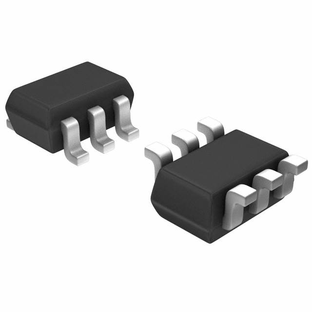
NPN+PNP, SOT-363, DUAL DIGITAL TRANSISTOR (BIAS RESISTOR BUILT-IN TRANSISTOR)
Deep-Dive with AI
Search across all available documentation for this part.
UMD3NTR
ActiveRohm Semiconductor
NPN+PNP, SOT-363, DUAL DIGITAL TRANSISTOR (BIAS RESISTOR BUILT-IN TRANSISTOR)
Deep-Dive with AI
Technical Specifications
Parameters and characteristics for this part
| Specification | UMD3NTR |
|---|---|
| Current - Collector (Ic) (Max) [Max] | 100 mA |
| Current - Collector Cutoff (Max) [Max] | 500 nA |
| DC Current Gain (hFE) (Min) @ Ic, Vce | 30 hFE |
| Frequency - Transition | 250 MHz |
| Mounting Type | Surface Mount |
| Package / Case | 6-TSSOP, SC-88, SOT-363 |
| Resistor - Emitter Base (R2) | 10 kOhms |
| Supplier Device Package | UMT6 |
| Transistor Type | 1 NPN, 1 PNP |
| Vce Saturation (Max) @ Ib, Ic | 300 mV |
| Voltage - Collector Emitter Breakdown (Max) [Max] | 50 V |
Pricing
Prices provided here are for design reference only. For realtime values and availability, please visit the distributors directly
Description
General part information
UMD3N Series
Devices integrating two transistors are available in ultra-compact packages, suitable for various applications such as pre-amplifier differential amplification circuits, high-frequency oscillators, driver ICs and so forth.
Documents
Technical documentation and resources