RSX051VYM30FHTR
ActiveRohm Semiconductor
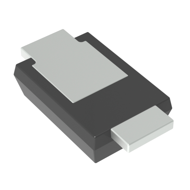
SMALL SIGNAL SCHOTTKY DIODE, SINGLE, 30 V, 500 MA, 390 MV, 5 A, 150 °C
Deep-Dive with AI
Search across all available documentation for this part.
RSX051VYM30FHTR
ActiveRohm Semiconductor
SMALL SIGNAL SCHOTTKY DIODE, SINGLE, 30 V, 500 MA, 390 MV, 5 A, 150 °C
Deep-Dive with AI
Technical Specifications
Parameters and characteristics for this part
| Specification | RSX051VYM30FHTR |
|---|---|
| Current - Average Rectified (Io) | 500 mA |
| Current - Reverse Leakage @ Vr | 200 µA |
| Grade | Automotive |
| Mounting Type | Surface Mount |
| Operating Temperature - Junction | 150 °C |
| Package / Case | 2-SMD, Flat Leads |
| Qualification | AEC-Q101 |
| Reverse Recovery Time (trr) | 9.6 ns |
| Speed | 200 mA, 500 ns |
| Supplier Device Package | TUMD2M |
| Technology | Schottky |
| Voltage - DC Reverse (Vr) (Max) [Max] | 30 V |
| Voltage - Forward (Vf) (Max) @ If [Max] | 390 mV |
Pricing
Prices provided here are for design reference only. For realtime values and availability, please visit the distributors directly
| Distributor | Package | Quantity | $ | |
|---|---|---|---|---|
| Digikey | Cut Tape (CT) | 1 | $ 0.38 | |
| 10 | $ 0.27 | |||
| 100 | $ 0.13 | |||
| 500 | $ 0.11 | |||
| 1000 | $ 0.08 | |||
| Digi-Reel® | 1 | $ 0.38 | ||
| 10 | $ 0.27 | |||
| 100 | $ 0.13 | |||
| 500 | $ 0.11 | |||
| 1000 | $ 0.08 | |||
| Tape & Reel (TR) | 3000 | $ 0.07 | ||
| 6000 | $ 0.07 | |||
| 9000 | $ 0.06 | |||
| 30000 | $ 0.06 | |||
| 75000 | $ 0.05 | |||
| 150000 | $ 0.05 | |||
Description
General part information
RSX051VYM30FH Series
RSX051VYM30 is small mold type (TUMD2M) schottky barrier diode for general rectification.
Documents
Technical documentation and resources