SH8KA7GZETB
ActiveRohm Semiconductor
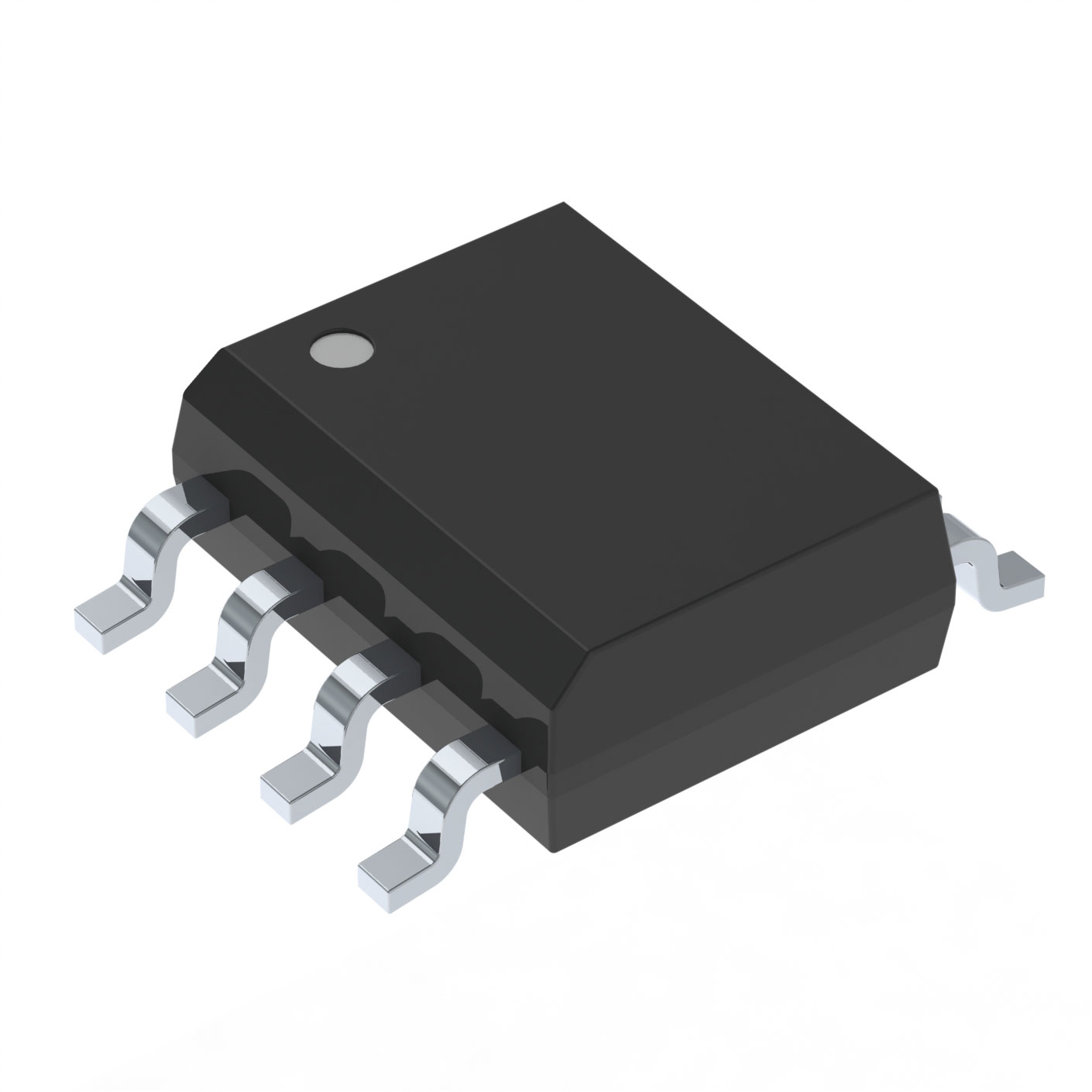
POWER FIELD-EFFECT TRANSISTOR, 30V, 0.0093OHM, 2-ELEMENT, N-CHANNEL, SILICON, METAL-OXIDE SEMICONDUCTOR FET, SOP-8
Deep-Dive with AI
Search across all available documentation for this part.
SH8KA7GZETB
ActiveRohm Semiconductor
POWER FIELD-EFFECT TRANSISTOR, 30V, 0.0093OHM, 2-ELEMENT, N-CHANNEL, SILICON, METAL-OXIDE SEMICONDUCTOR FET, SOP-8
Deep-Dive with AI
Technical Specifications
Parameters and characteristics for this part
| Specification | SH8KA7GZETB |
|---|---|
| Configuration | 2 N-Channel (Dual) |
| Current - Continuous Drain (Id) @ 25°C | 15 A |
| Drain to Source Voltage (Vdss) | 30 V |
| Gate Charge (Qg) (Max) @ Vgs | 81 nC |
| Input Capacitance (Ciss) (Max) @ Vds | 3320 pF |
| Mounting Type | Surface Mount |
| Operating Temperature | 150 °C |
| Package / Case | 8-SOIC |
| Package / Case [x] | 0.154 in |
| Package / Case [y] | 3.9 mm |
| Power - Max [Max] | 2 W |
| Rds On (Max) @ Id, Vgs | 9.3 mOhm |
| Supplier Device Package | 8-SOP |
| Technology | MOSFET (Metal Oxide) |
| Vgs(th) (Max) @ Id [Max] | 2.5 V |
Pricing
Prices provided here are for design reference only. For realtime values and availability, please visit the distributors directly
| Distributor | Package | Quantity | $ | |
|---|---|---|---|---|
| Digikey | Cut Tape (CT) | 1 | $ 1.92 | |
| 10 | $ 1.59 | |||
| 100 | $ 1.27 | |||
| 500 | $ 1.07 | |||
| 1000 | $ 0.91 | |||
| Digi-Reel® | 1 | $ 1.92 | ||
| 10 | $ 1.59 | |||
| 100 | $ 1.27 | |||
| 500 | $ 1.07 | |||
| 1000 | $ 0.91 | |||
| Tape & Reel (TR) | 2500 | $ 0.82 | ||
| 5000 | $ 0.81 | |||
Description
General part information
SH8KA7 Series
SH8KA7 is low on-resistance and small surface mount package MOSFET for switching and motor drive application.
Documents
Technical documentation and resources