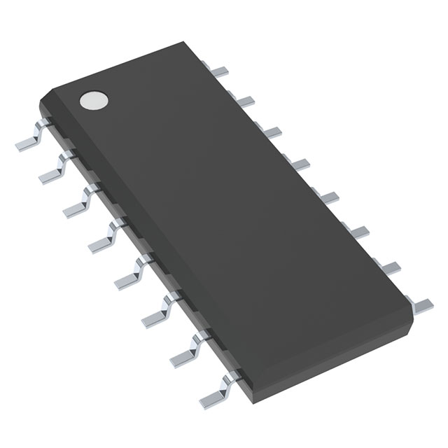
UCC3585D
LTBLOW VOLTAGE SYNCHRONOUS BUCK CONTROLLER
Deep-Dive with AI
Search across all available documentation for this part.

UCC3585D
LTBLOW VOLTAGE SYNCHRONOUS BUCK CONTROLLER
Deep-Dive with AI
Technical Specifications
Parameters and characteristics for this part
| Specification | UCC3585D |
|---|---|
| Clock Sync | False |
| Control Features | Enable, Soft Start, Frequency Control, Current Limit |
| Duty Cycle (Max) [Max] | 100 % |
| Frequency - Switching | 500 kHz |
| Function | Step-Down |
| Mounting Type | Surface Mount |
| Number of Outputs | 1 |
| Operating Temperature [Max] | 85 C |
| Operating Temperature [Min] | 0 °C |
| Output Configuration | Positive |
| Output Phases | 1 |
| Output Type | Transistor Driver |
| Package / Case | 16-SOIC |
| Package / Case [x] | 0.154 in |
| Package / Case [y] | 3.9 mm |
| Supplier Device Package | 16-SOIC |
| Synchronous Rectifier | True |
| Topology | Buck |
| Voltage - Supply (Vcc/Vdd) [Max] | 5.5 V |
| Voltage - Supply (Vcc/Vdd) [Min] | 3 V |
Pricing
Prices provided here are for design reference only. For realtime values and availability, please visit the distributors directly
| Distributor | Package | Quantity | $ | |
|---|---|---|---|---|
| Digikey | Tube | 280 | $ 3.53 | |
| Texas Instruments | TUBE | 1 | $ 3.81 | |
| 100 | $ 3.10 | |||
| 250 | $ 2.44 | |||
| 1000 | $ 2.07 | |||
Description
General part information
UCC3585 Series
The UCC3585 synchronous buck controller provides flexible high efficiency power conversion for output voltages as low as 0.9 V with ensured ±1% dc accuracy. With an input voltage range of 3.0 V to 5.5 V, it is the ideal choice for 3.3 V only, 5.0 V only, or other low voltage systems. The fixed frequency oscillator is capable of providing practical PWM operation to 500 kHz.
The UCC3585 drives a complementary pair of power MOSFET transistors. A P-channel on the high side, and an N-channel on the low side step down the input voltage at up to 90% efficiency.
A programmable two-level current limiting function is provided by sensing the voltage drop across the high side P-channel MOSFET. This circuit can be configured to provide pulse-by-pulse limiting, timed shutdown after seven consecutive faults, or latch-off after fault detection, allowing maximum application flexibility. The current limit threshold can be programmed over a wide range with a single resistor.
Documents
Technical documentation and resources


