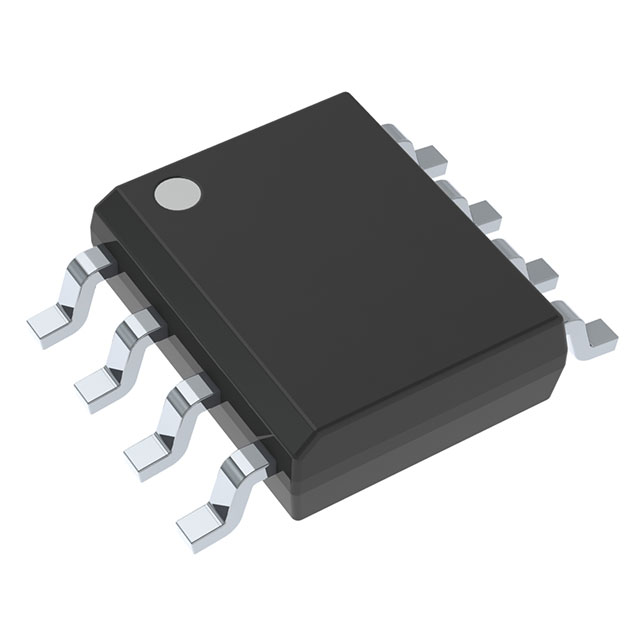
UC2714D
Active0.5-A/1-A DUAL-CHANNEL GATE DRIVER WITH SINGLE INPUT AND DEAD TIME CONTROL
Deep-Dive with AI
Search across all available documentation for this part.

UC2714D
Active0.5-A/1-A DUAL-CHANNEL GATE DRIVER WITH SINGLE INPUT AND DEAD TIME CONTROL
Deep-Dive with AI
Technical Specifications
Parameters and characteristics for this part
| Specification | UC2714D |
|---|---|
| Channel Type | Synchronous |
| Current - Peak Output (Source, Sink) [custom] | 2 A |
| Current - Peak Output (Source, Sink) [custom] | 1 A |
| Driven Configuration | Low-Side |
| Gate Type | N-Channel, P-Channel MOSFET |
| Input Type | Non-Inverting |
| Logic Voltage - VIL, VIH | 0.8 V, 2 V |
| Mounting Type | Surface Mount |
| Number of Drivers | 2 |
| Operating Temperature [Max] | 150 °C |
| Operating Temperature [Min] | -40 °C |
| Package / Case | 8-SOIC |
| Package / Case [x] | 0.154 in |
| Package / Case [y] | 3.9 mm |
| Rise / Fall Time (Typ) [custom] | 25 ns |
| Rise / Fall Time (Typ) [custom] | 30 ns |
| Supplier Device Package | 8-SOIC |
| Voltage - Supply [Max] | 20 V |
| Voltage - Supply [Min] | 7 V |
Pricing
Prices provided here are for design reference only. For realtime values and availability, please visit the distributors directly
| Distributor | Package | Quantity | $ | |
|---|---|---|---|---|
| Digikey | Tube | 375 | $ 2.71 | |
| Texas Instruments | TUBE | 1 | $ 3.37 | |
| 100 | $ 2.95 | |||
| 250 | $ 2.07 | |||
| 1000 | $ 1.67 | |||
Description
General part information
UC2714 Series
These two families of high speed drivers are designed to provide drive waveforms for complementary switches. Complementary switch configurations are commonly used in synchronous rectification circuits and active clamp/reset circuits, which provide zero voltage switching. In order to facilitate the soft switching transitions, independently programmable delays between the two output waveforms are provided on these drivers. The delay pins also have true-zero voltage-sensing capability which allows immediate activation of the corresponding switch when zero voltage is applied. These devices require a PWM-type input to operate and interface with commonly available PWM controllers.
In the UC1714 series, the AUX output is inverted to allow driving a p-channel MOSFET. In the UC1715 series, the two outputs are configured in a true complementary fashion.
These two families of high speed drivers are designed to provide drive waveforms for complementary switches. Complementary switch configurations are commonly used in synchronous rectification circuits and active clamp/reset circuits, which provide zero voltage switching. In order to facilitate the soft switching transitions, independently programmable delays between the two output waveforms are provided on these drivers. The delay pins also have true-zero voltage-sensing capability which allows immediate activation of the corresponding switch when zero voltage is applied. These devices require a PWM-type input to operate and interface with commonly available PWM controllers.
Documents
Technical documentation and resources


