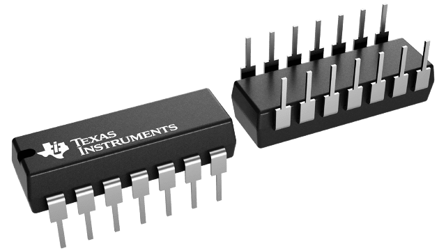
UC3901N
ActiveFB GENERATOR ISOLATED FB GENERATOR 14-PIN PDIP TUBE
Deep-Dive with AI
Search across all available documentation for this part.

UC3901N
ActiveFB GENERATOR ISOLATED FB GENERATOR 14-PIN PDIP TUBE
Deep-Dive with AI
Technical Specifications
Parameters and characteristics for this part
| Specification | UC3901N |
|---|---|
| Applications | Feedback Generator |
| Current - Supply | 5 mA |
| Mounting Type | Through Hole |
| Operating Temperature [Max] | 70 °C |
| Operating Temperature [Min] | 0 °C |
| Package / Case | 14-DIP |
| Package / Case [x] | 0.3 " |
| Package / Case [y] | 7.62 mm |
| Voltage - Supply [Max] | 40 VDC |
| Voltage - Supply [Min] | 4.5 V |
Pricing
Prices provided here are for design reference only. For realtime values and availability, please visit the distributors directly
| Distributor | Package | Quantity | $ | |
|---|---|---|---|---|
| Arrow | N/A | 25 | $ 4.74 | |
| Digikey | Tube | 1 | $ 7.05 | |
| 10 | $ 6.37 | |||
| 25 | $ 6.07 | |||
| 100 | $ 5.27 | |||
| 250 | $ 5.04 | |||
| 500 | $ 4.59 | |||
| 1000 | $ 4.00 | |||
| 2500 | $ 3.85 | |||
| Texas Instruments | TUBE | 1 | $ 6.25 | |
| 100 | $ 5.09 | |||
| 250 | $ 4.00 | |||
| 1000 | $ 3.39 | |||
Description
General part information
UC3901 Series
The UC1901 family is designed to solve many of the problems associated with closing a feedback control loop across a voltage isolation boundary. As a stable and reliable alternative to an optical coupler, these devices feature an amplitude modulation system which allows a loop error signal to be coupled with a small RF transformer or capacitor.
The programmable, high-frequency oscillator within the UC1901 series permits the use of smaller, less expensive transformers which can readily be built to meet the isolation requirements of today's line-operated power systems. As an alternative to RF operation, the external clock input to these devices allows synchronization to a system clock or to the switching frequency of a SMPS.
An additional feature is a status monitoring circuit which provides an active-low output when the sensed error voltage is within ±10% of the reference. The DRIVERA output, DRIVERB output, and STATUS output are disabled until the input supply has reached a sufficient level to allow proper operation of the device.
Documents
Technical documentation and resources


