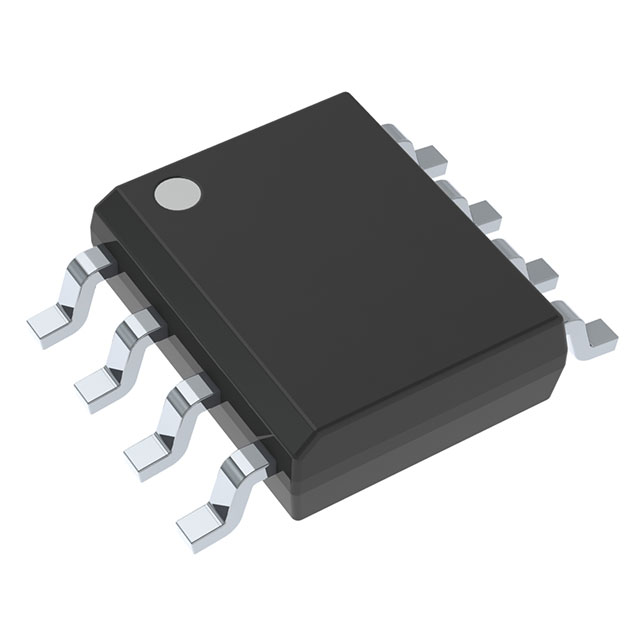
UCC2807DTR-1
ActiveECONOMY LOW POWER BICMOS 1MHZ CURRENT MODE PWM WITH 7.2V/6.9V UVLO, PROG DUTY CYCLE, -40C TO 85C
Deep-Dive with AI
Search across all available documentation for this part.

UCC2807DTR-1
ActiveECONOMY LOW POWER BICMOS 1MHZ CURRENT MODE PWM WITH 7.2V/6.9V UVLO, PROG DUTY CYCLE, -40C TO 85C
Deep-Dive with AI
Technical Specifications
Parameters and characteristics for this part
| Specification | UCC2807DTR-1 |
|---|---|
| Clock Sync | False |
| Duty Cycle (Max) [Max] | 78 % |
| Frequency - Switching | 202 kHz |
| Function | Step-Up, Step-Up/Step-Down |
| Mounting Type | Surface Mount |
| Number of Outputs | 1 |
| Operating Temperature [Max] | 85 °C |
| Operating Temperature [Min] | -40 °C |
| Output Configuration | Positive |
| Output Phases | 1 |
| Output Type | Transistor Driver |
| Package / Case | 8-SOIC |
| Package / Case [x] | 0.154 in |
| Package / Case [y] | 3.9 mm |
| Supplier Device Package | 8-SOIC |
| Synchronous Rectifier | False |
| Topology | Flyback, Boost, Forward Converter |
| Voltage - Supply (Vcc/Vdd) [Max] | 13.5 V |
| Voltage - Supply (Vcc/Vdd) [Min] | 6.9 V |
UCC2807-2 Series
Economy low power BICMOS 1MHz current mode PWM with 12.5V/8.3V UVLO, Prog duty cycle, -40C to 85C
| Part | Voltage - Start Up | Operating Temperature [Min] | Operating Temperature [Max] | Mounting Type | Frequency - Switching | Fault Protection | Topology | Output Isolation | Duty Cycle | Internal Switch(s) | Supplier Device Package | Package / Case | Package / Case | Package / Case | Voltage - Supply (Vcc/Vdd) [Min] | Voltage - Supply (Vcc/Vdd) [Max] | Function | Output Configuration | Synchronous Rectifier | Clock Sync | Duty Cycle (Max) [Max] | Number of Outputs | Package / Case [y] | Package / Case [x] | Output Phases | Output Type |
|---|---|---|---|---|---|---|---|---|---|---|---|---|---|---|---|---|---|---|---|---|---|---|---|---|---|---|
Texas Instruments | 12.5 V | -55 °C | 150 °C | Through Hole | 1 MHz | Current Limiting | Boost Flyback Forward | Isolated | 78 % | 8-PDIP | 0.3 in | 8-DIP | 7.62 mm | |||||||||||||
Texas Instruments | -40 °C | 85 °C | Surface Mount | 202 kHz | Boost Flyback Forward Converter | 8-SOIC | 8-SOIC | 4.1 V | 13.5 V | Step-Up Step-Up/Step-Down | Positive | 78 % | 1 | 3.9 mm | 0.154 in | 1 | Transistor Driver | |||||||||
Texas Instruments | -40 °C | 85 °C | Surface Mount | 202 kHz | Boost Flyback Forward Converter | 8-SOIC | 8-SOIC | 4.1 V | 13.5 V | Step-Up Step-Up/Step-Down | Positive | 78 % | 1 | 3.9 mm | 0.154 in | 1 | Transistor Driver | |||||||||
Texas Instruments | ||||||||||||||||||||||||||
Texas Instruments | -40 °C | 85 °C | Through Hole | 202 kHz | Boost Flyback Forward Converter | 8-PDIP | 0.3 in | 8-DIP | 7.62 mm | 6.9 V | 13.5 V | Step-Up Step-Up/Step-Down | Positive | 78 % | 1 | 1 | Transistor Driver | |||||||||
Texas Instruments | 12.5 V | -55 °C | 150 °C | Surface Mount | 1 MHz | Current Limiting | Boost Flyback Forward | Isolated | 78 % | 8-SOIC | 8-SOIC | 3.9 mm | 0.154 in | |||||||||||||
Texas Instruments | -40 °C | 85 °C | Surface Mount | 202 kHz | Boost Flyback Forward Converter | 8-SOIC | 8-SOIC | 4.1 V | 13.5 V | Step-Up Step-Up/Step-Down | Positive | 78 % | 1 | 3.9 mm | 0.154 in | 1 | Transistor Driver | |||||||||
Texas Instruments | -40 °C | 85 °C | Surface Mount | 202 kHz | Boost Flyback Forward Converter | 8-SOIC | 8-SOIC | 6.9 V | 13.5 V | Step-Up Step-Up/Step-Down | Positive | 78 % | 1 | 3.9 mm | 0.154 in | 1 | Transistor Driver |
Pricing
Prices provided here are for design reference only. For realtime values and availability, please visit the distributors directly
| Distributor | Package | Quantity | $ | |
|---|---|---|---|---|
| Digikey | Cut Tape (CT) | 1 | $ 5.10 | |
| 10 | $ 4.58 | |||
| 25 | $ 4.33 | |||
| 100 | $ 3.76 | |||
| 250 | $ 3.56 | |||
| 500 | $ 3.20 | |||
| 1000 | $ 2.70 | |||
| Digi-Reel® | 1 | $ 5.10 | ||
| 10 | $ 4.58 | |||
| 25 | $ 4.33 | |||
| 100 | $ 3.76 | |||
| 250 | $ 3.56 | |||
| 500 | $ 3.20 | |||
| 1000 | $ 2.70 | |||
| Tape & Reel (TR) | 2500 | $ 2.56 | ||
| Texas Instruments | LARGE T&R | 1 | $ 4.43 | |
| 100 | $ 3.88 | |||
| 250 | $ 2.72 | |||
| 1000 | $ 2.19 | |||
Description
General part information
UCC2807-2 Series
The UCC3807 family of high speed, low power integrated circuits contains all of the control and drive circuitry required for off-line and dc-to-dc fixed frequency current mode switching power supplies with minimal external parts count.
These devices are similar to the UCC3800 family, but with the added feature of a user programmable maximum duty cycle. Oscillator frequency and maximum duty cycle are programmed with two resistors and a capacitor. The UCC3807 family also features internal full cycle soft start and internal leading edge blanking of the current sense input.
The UCC3807 family offers a variety of package options, temperature range options, and choice of critical voltage levels. The family has UVLO thresholds and hysteresis levels for off-line and battery powered systems. Thresholds are shown in the table below.
Documents
Technical documentation and resources


