UMZ18NFHT106
ActiveRohm Semiconductor
ZENER ARRAYS FOR TERMINAL PROTECTION DEVICES (AEC-Q101 QUALIFIED)
Deep-Dive with AI
Search across all available documentation for this part.
UMZ18NFHT106
ActiveRohm Semiconductor
ZENER ARRAYS FOR TERMINAL PROTECTION DEVICES (AEC-Q101 QUALIFIED)
Deep-Dive with AI
Technical Specifications
Parameters and characteristics for this part
| Specification | UMZ18NFHT106 |
|---|---|
| Configuration | 1 Pair Common Anode |
| Current - Reverse Leakage @ Vr | 100 nA |
| Grade | Automotive |
| Mounting Type | Surface Mount |
| Operating Temperature | 150 °C |
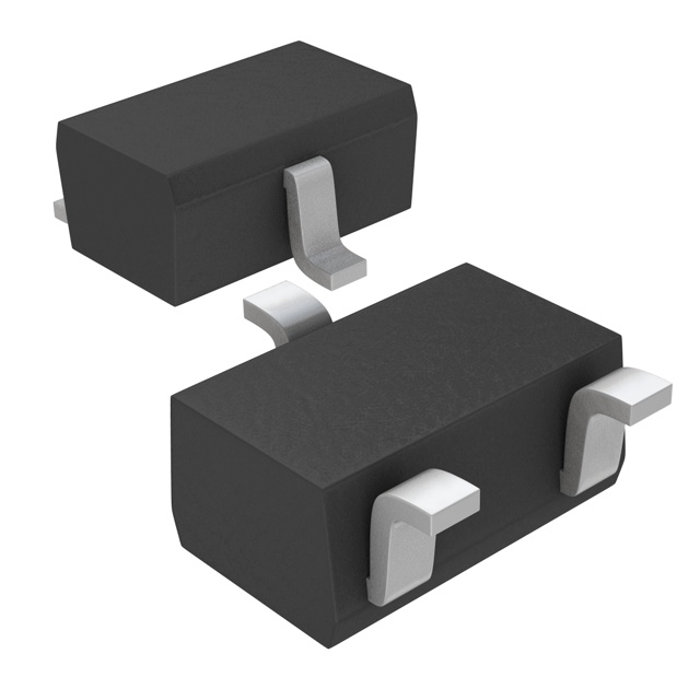
| Package / Case | SC-70, SOT-323 |
| Power - Max [Max] | 200 mW |
| Qualification | AEC-Q101 |
| Supplier Device Package | UMD3 |
| Tolerance | 2.19 % |
| Voltage - Zener (Nom) (Vz) | 18 V |
Pricing
Prices provided here are for design reference only. For realtime values and availability, please visit the distributors directly
| Distributor | Package | Quantity | $ | |
|---|---|---|---|---|
| Digikey | Cut Tape (CT) | 1 | $ 0.43 | |
| 10 | $ 0.29 | |||
| 100 | $ 0.20 | |||
| 500 | $ 0.15 | |||
| 1000 | $ 0.14 | |||
| Digi-Reel® | 1 | $ 0.43 | ||
| 10 | $ 0.29 | |||
| 100 | $ 0.20 | |||
| 500 | $ 0.15 | |||
| 1000 | $ 0.14 | |||
| Tape & Reel (TR) | 3000 | $ 0.10 | ||
| 6000 | $ 0.10 | |||
| 9000 | $ 0.10 | |||
| Newark | Each (Supplied on Cut Tape) | 1 | $ 0.45 | |
| 10 | $ 0.30 | |||
| 25 | $ 0.27 | |||
| 50 | $ 0.24 | |||
| 100 | $ 0.20 | |||
| 250 | $ 0.18 | |||
| 500 | $ 0.16 | |||
| 1000 | $ 0.14 | |||
Description
General part information
UMZ18NFH Series
ROHM's zener diodes are available in various lineup as 2-pin mold surface mount type and complex type.
Documents
Technical documentation and resources