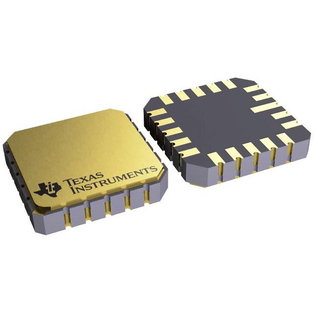
SN54LS628J
ActiveVOLTAGE-CONTROLLED OSCILLATORS 1
Deep-Dive with AI
Search across all available documentation for this part.

SN54LS628J
ActiveVOLTAGE-CONTROLLED OSCILLATORS 1
Technical Specifications
Parameters and characteristics for this part
| Specification | SN54LS628J |
|---|---|
| Current - Supply | 20 mA |
| Frequency [Max] | 25 MHz |
| Frequency [Min] | 15 MHz |
| Mounting Type | Through Hole |
| Operating Temperature [Max] | 125 °C |
| Operating Temperature [Min] | -55 °C |
| Package / Case | 14-CDIP |
| Supplier Device Package | 14-CDIP |
| Type | VCO |
| Voltage - Supply [Max] | 5.5 V |
| Voltage - Supply [Min] | 4.5 V |
Pricing
Prices provided here are for design reference only. For realtime values and availability, please visit the distributors directly
| Distributor | Package | Quantity | $ | |
|---|---|---|---|---|
| Texas Instruments | TUBE | 1 | $ 23.06 | |
| 100 | $ 20.50 | |||
| 250 | $ 16.85 | |||
| 1000 | $ 15.07 | |||
Description
General part information
5962-9204601 Series
These voltage-controlled oscillators (VCOs) are improved versions of the original VCO family: SN54LS124, SN54LS324 thru SN54LS327, SN74LS124, and SN74LS324 thru SN74LS327. These new devices feature improved voltage-to-frequency linearity, range, and compensation. With the exception of the 'LS624 and 'LS628, all of these devices feature two independent VCOs in a single monolithic chip. The 'LS624, 'LS625, 'LS626, and 'LS628 have complementary Z outputs. The output frequency for each VCO is established by a single external component (either a capacitor or crystal) in combination with voltage-sensitive inputs used for frequency control and frequency range. Each device has a voltage-sensitive input for frequency control; however, the 'LS624, 'LS628, and 'LS629 devices also have one for frequency range. (See Figures 1 thru 6).
The 'LS628 offers more precise temperature compensation than its 'LS624 counterpart. The 'LS624 features a 600 ohm internal timing resistor. The 'LS628 requires a timing resistor to be connected externally across Rextpins. Temperature compensation will be improved due to the temperature coefficient of the external resistor.
Figure 3 and Figure 6 contain the necessary information to choose the proper capacitor value to obtain the desired operating frequency.
Documents
Technical documentation and resources


