UC2909DWTR
ObsoleteIC BATT CHG LEAD ACID 20SOIC
Deep-Dive with AI
Search across all available documentation for this part.
UC2909DWTR
ObsoleteIC BATT CHG LEAD ACID 20SOIC
Deep-Dive with AI
Technical Specifications
Parameters and characteristics for this part
| Specification | UC2909DWTR |
|---|---|
| Battery Chemistry | Lead Acid |
| Current - Charging | Constant - Programmable |
| Mounting Type | Surface Mount |
| Operating Temperature [Max] | 85 °C |
| Operating Temperature [Min] | -40 °C |
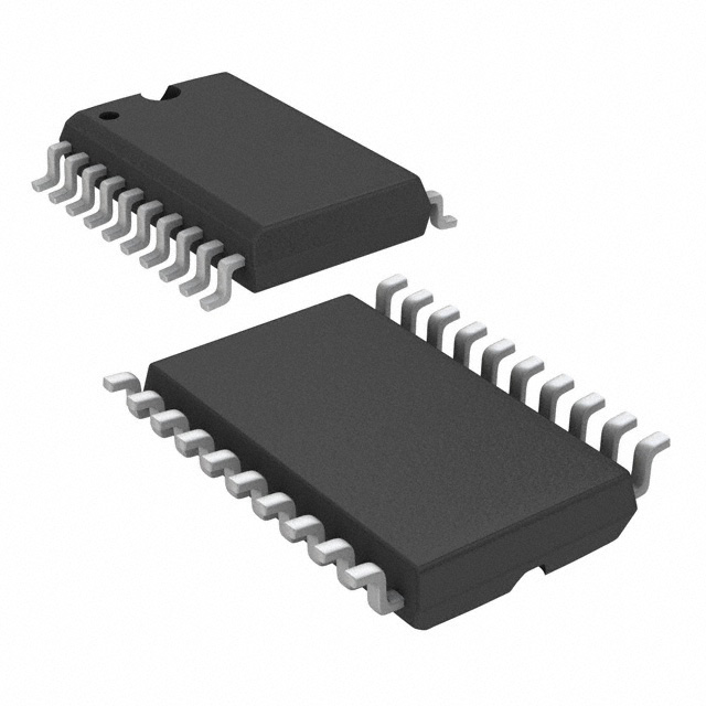
| Package / Case | 20-SOIC |
| Package / Case [y] | 0.295 in |
| Package / Case [y] | 7.5 mm |
| Supplier Device Package | 20-SOIC |
| Voltage - Supply (Max) [Max] | 40 V |
Pricing
Prices provided here are for design reference only. For realtime values and availability, please visit the distributors directly
| Distributor | Package | Quantity | $ | |
|---|---|---|---|---|
Description
General part information
UC2909-EP Series
The UC2909 controls lead acid battery charging with a highly efficient average current mode control loop. This chip combines charge state logic with average current PWM control circuitry. Charge state logic commands current or voltage control depending on the charge state. The chip includes undervoltage lockout circuitry to insure sufficient supply voltage is present before output switching starts. Additional circuit blocks include a differential current sense amplifier, a 1.5% voltage reference, a –3.9-mV/°C thermistor linearization circuit, voltage and current error amplifiers, a PWM oscillator, a PWM comparator, a PWM latch, charge state decode bits, and a 100-mA open collector output driver.
The UC2909 controls lead acid battery charging with a highly efficient average current mode control loop. This chip combines charge state logic with average current PWM control circuitry. Charge state logic commands current or voltage control depending on the charge state. The chip includes undervoltage lockout circuitry to insure sufficient supply voltage is present before output switching starts. Additional circuit blocks include a differential current sense amplifier, a 1.5% voltage reference, a –3.9-mV/°C thermistor linearization circuit, voltage and current error amplifiers, a PWM oscillator, a PWM comparator, a PWM latch, charge state decode bits, and a 100-mA open collector output driver.
Documents
Technical documentation and resources