UCC27538DBVT
Active2.5-A/5-A SINGLE-CHANNEL GATE DRIVER WITH 8-V UVLO, 35-V VDD, AND DUAL INPUT
Deep-Dive with AI
Search across all available documentation for this part.
UCC27538DBVT
Active2.5-A/5-A SINGLE-CHANNEL GATE DRIVER WITH 8-V UVLO, 35-V VDD, AND DUAL INPUT
Technical Specifications
Parameters and characteristics for this part
| Specification | UCC27538DBVT |
|---|---|
| Channel Type | Single |
| Current - Peak Output (Source, Sink) [custom] | 2.5 A |
| Current - Peak Output (Source, Sink) [custom] | 5 A |
| Driven Configuration | Low-Side |
| Gate Type | N-Channel MOSFET, IGBT, MOSFET |
| Input Type | Non-Inverting |
| Mounting Type | Surface Mount |
| Number of Drivers | 1 |
| Operating Temperature [Max] | 140 °C |
| Operating Temperature [Min] | -40 °C |
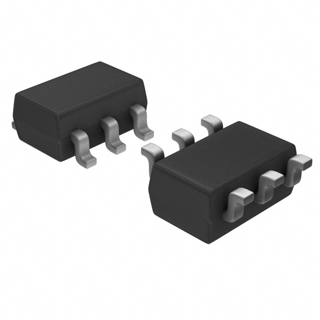
| Package / Case | SOT-23-6 |
| Rise / Fall Time (Typ) [custom] | 7 ns |
| Rise / Fall Time (Typ) [custom] | 15 ns |
| Supplier Device Package | SOT-23-6 |
| Voltage - Supply [Max] | 32 VDC |
| Voltage - Supply [Min] | 10 VDC |
Pricing
Prices provided here are for design reference only. For realtime values and availability, please visit the distributors directly
| Distributor | Package | Quantity | $ | |
|---|---|---|---|---|
| Digikey | Cut Tape (CT) | 1 | $ 1.54 | |
| 10 | $ 1.38 | |||
| 25 | $ 1.30 | |||
| 100 | $ 1.11 | |||
| Digi-Reel® | 1 | $ 1.54 | ||
| 10 | $ 1.38 | |||
| 25 | $ 1.30 | |||
| 100 | $ 1.11 | |||
| Tape & Reel (TR) | 250 | $ 1.04 | ||
| 500 | $ 0.91 | |||
| 750 | $ 0.76 | |||
| 1250 | $ 0.76 | |||
| 1750 | $ 0.73 | |||
| 2500 | $ 0.70 | |||
| 6250 | $ 0.68 | |||
| 12500 | $ 0.65 | |||
| Texas Instruments | SMALL T&R | 1 | $ 1.27 | |
| 100 | $ 0.98 | |||
| 250 | $ 0.72 | |||
| 1000 | $ 0.52 | |||
Description
General part information
UCC27538 Series
The UCC2753x single-channel, high-speed gate drivers can effectively drive MOSFET and IGBT power switches. Using a design that allows for a source of up to 2.5 A and 5-A sink through asymmetrical drive (split outputs), coupled with the ability to support a negative turn-off bias, rail-to-rail drive capability, extremely small propagation delay (17 ns typical), the UCC2753x devices are ideal solutions for MOSFET and IGBT power switches. The UCC2753x family of devices can also support enable, dual input, and inverting and non-inverting input functionality. The split outputs and strong asymmetrical drive boost the devices immunity against parasitic Miller turn-on effect and can help reduce ground debouncing.
Leaving the input pin open holds the driver output low. The logic behavior of the driver is shown in the application diagram, timing diagram, and input and output logic truth table.
Internal circuitry on VDD pin provides an undervoltage lockout function that holds output low until VDD supply voltage is within operating range.
Documents
Technical documentation and resources