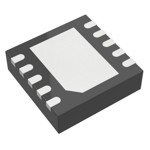
LTC3568IDD#PBF
Active1.8A, 4MHZ, SYNCHRONOUS STEP-DOWN DC/DC CONVERTER
Deep-Dive with AI
Search across all available documentation for this part.

LTC3568IDD#PBF
Active1.8A, 4MHZ, SYNCHRONOUS STEP-DOWN DC/DC CONVERTER
Deep-Dive with AI
Technical Specifications
Parameters and characteristics for this part
| Specification | LTC3568IDD#PBF |
|---|---|
| Current - Output | 1.8 A |
| Frequency - Switching [Max] | 4 MHz |
| Function | Step-Down |
| Mounting Type | Surface Mount |
| Number of Outputs | 1 |
| Operating Temperature [Max] | 125 ¯C |
| Operating Temperature [Min] | -40 °C |
| Output Configuration | Positive |
| Output Type | Adjustable |
| Package / Case | 10-WFDFN Exposed Pad |
| Supplier Device Package | 10-DFN (3x3) |
| Synchronous Rectifier | True |
| Topology | Buck |
| Voltage - Input (Max) [Max] | 5.5 V |
| Voltage - Input (Min) [Min] | 2.25 V |
| Voltage - Output (Max) | 5 V |
| Voltage - Output (Min/Fixed) | 0.8 V |
Pricing
Prices provided here are for design reference only. For realtime values and availability, please visit the distributors directly
| Distributor | Package | Quantity | $ | |
|---|---|---|---|---|
| Digikey | Tube | 1 | $ 11.38 | |
| 10 | $ 7.97 | |||
| 25 | $ 7.10 | |||
| 100 | $ 6.12 | |||
| 250 | $ 5.64 | |||
| 500 | $ 5.35 | |||
| 1000 | $ 5.11 | |||
Description
General part information
LTC3568 Series
The LTC3568 is a constant frequency, synchronous step- down DC/DC converter. Intended for medium power applications, it operates from a 2.5V to 5.5V input voltage range and has a user configurable operating frequency up to 4MHz, allowing the use of tiny, low cost capacitors and inductors 2mm or less in height. The output voltage is adjustable from 0.8V to 5V. Internal sychronous 0.11Ω power switches with 2.4A peak current ratings provide high efficiency. The LTC3568’s current mode architecture and external compensation allow the transient response to be optimized over a wide range of loads and output capacitors.The LTC3568 can be configured for automatic power saving Burst Mode operation to reduce gate charge losses when the load current drops below the level required for continuous operation. For reduced noise and RF interference, the SYNC/MODE pin can be configured to skip pulses or provide forced continuous operation.To further maximize battery life, the P-channel MOSFET is turned on continuously in dropout (100% duty cycle) with a low quiescent current of 60μA. In shutdown, the device draws <1μA.ApplicationsNotebook ComputersDigital CamerasCellular PhonesHandheld InstrumentsBoard Mounted Power Supplies
Documents
Technical documentation and resources


