VFC320CP
ActiveVOLTAGE-TO-FREQUENCY AND FREQUENCY-TO-VOLTAGE CONVERTER WITH 0.1% LINEARITY ERROR AT 1 MHZ
Deep-Dive with AI
Search across all available documentation for this part.
VFC320CP
ActiveVOLTAGE-TO-FREQUENCY AND FREQUENCY-TO-VOLTAGE CONVERTER WITH 0.1% LINEARITY ERROR AT 1 MHZ
Deep-Dive with AI
Technical Specifications
Parameters and characteristics for this part
| Specification | VFC320CP |
|---|---|
| Frequency - Max [Max] | 1 MHz |
| Full Scale | 20 ppm/°C |
| Linearity | 0.1 % |
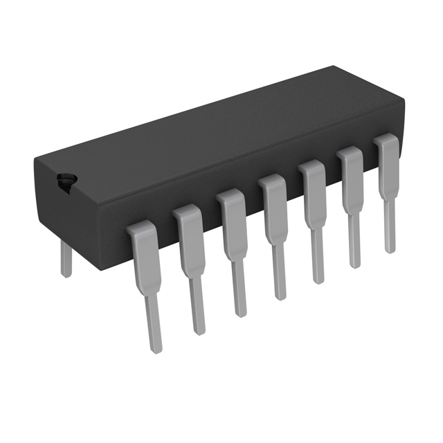
| Mounting Type | Through Hole |
| Package / Case | 14-DIP |
| Package / Case [x] | 0.3 " |
| Package / Case [y] | 7.62 mm |
| Type | Volt to Frequency and Frequency to Volt |
Pricing
Prices provided here are for design reference only. For realtime values and availability, please visit the distributors directly
| Distributor | Package | Quantity | $ | |
|---|---|---|---|---|
| Digikey | Tube | 1 | $ 33.64 | |
| 10 | $ 31.03 | |||
| 25 | $ 29.63 | |||
| 100 | $ 26.49 | |||
| 250 | $ 25.27 | |||
| Texas Instruments | TUBE | 1 | $ 30.49 | |
| 100 | $ 27.11 | |||
| 250 | $ 22.28 | |||
| 1000 | $ 19.93 | |||
Description
General part information
VFC320 Series
The VFC320 monolithic voltage-to-frequency and frequency-to-voltage converter provides a simple low cost method of converting analog signals into digital pulses. The digital output is an open collector and the digital pulse train repetition rate is proportional to the amplitude of the analog input voltage. Output pulses are compatible with TTL, and CMOS logic families.
High linearity (0.005%, max at 10kHz FS) is achieved with relatively few external components. Two external resistors and two external capacitors are required to operate. Full scale frequency and input voltage are determined by a resistor in series with—In and two capacitors (one-shot timing and input amplifier integration). The other resistor is a non-critical open collector pull-up (fOUTto +VCC). The VFC320 is available in two performance grades. The VFC320 is specified for the –25°C to +85°C, range.
The VFC320 monolithic voltage-to-frequency and frequency-to-voltage converter provides a simple low cost method of converting analog signals into digital pulses. The digital output is an open collector and the digital pulse train repetition rate is proportional to the amplitude of the analog input voltage. Output pulses are compatible with TTL, and CMOS logic families.
Documents
Technical documentation and resources