UCC27425PG4
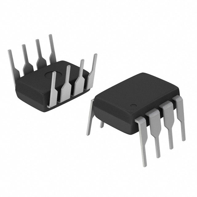
UnknownIC GATE DRVR LOW-SIDE 8DIP
Deep-Dive with AI
Search across all available documentation for this part.
UCC27425PG4
UnknownIC GATE DRVR LOW-SIDE 8DIP
Deep-Dive with AI
Technical Specifications
Parameters and characteristics for this part
| Specification | UCC27425PG4 |
|---|---|
| Channel Type | Independent |
| Current - Peak Output (Source, Sink) [custom] | 4 A |
| Current - Peak Output (Source, Sink) [custom] | 4 A |
| Driven Configuration | Low-Side |
| Gate Type | N-Channel, P-Channel MOSFET |
| Input Type | Non-Inverting, Inverting |
| Logic Voltage - VIL, VIH | 1 V, 2 V |
| Mounting Type | Through Hole |
| Number of Drivers | 2 |
| Operating Temperature [Max] | 125 °C |
| Operating Temperature [Min] | -40 °C |
| Package / Case | 0.3 in |
| Package / Case | 8-DIP |
| Package / Case | 7.62 mm |
| Rise / Fall Time (Typ) [custom] | 15 ns |
| Rise / Fall Time (Typ) [custom] | 20 ns |
| Supplier Device Package | 8-PDIP |
| Voltage - Supply [Max] | 15 V |
| Voltage - Supply [Min] | 4 V |
Pricing
Prices provided here are for design reference only. For realtime values and availability, please visit the distributors directly
| Distributor | Package | Quantity | $ | |
|---|---|---|---|---|
| Digikey | Tube | 500 | $ 0.96 | |
Description
General part information
UCC27425-Q1 Series
The UCC2742x family of high-speed dual MOSFET drivers can deliver large peak currents into capacitive loads. Three standard logic options are offered – dual-inverting, dual-noninverting, and one-inverting and one-noninverting driver. The thermally enhanced 8-pin PowerPAD™ MSOP package (DGN) drastically lowers the thermal resistance to improve long-term reliability. It is also offered in the standard SOIC-8 (D) or PDIP-8 (P) packages.
Using a design that inherently minimizes shoot-through current, these drivers deliver 4A of current where it is needed most at the Miller plateau region during the MOSFET switching transition. A unique BiPolar and MOSFET hybrid output stage in parallel also allows efficient current sourcing and sinking at low supply voltages.
The UCC2742x provides enable (ENB) functions to have better control of the operation of the driver applications. ENBA and ENBB are implemented on pins 1 and 8 which were previously left unused in the industry standard pin-out. They are internally pulled up to V DD for active high logic and can be left open for standard operation.
Documents
Technical documentation and resources
No documents available