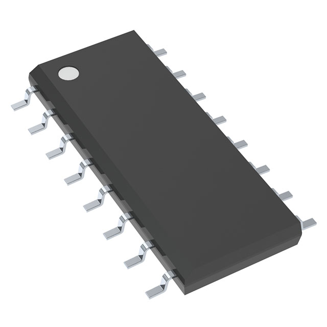
UCC3912DPG4
UnknownIC HOT SWAP CTRLR GP 16SOIC
Deep-Dive with AI
Search across all available documentation for this part.

UCC3912DPG4
UnknownIC HOT SWAP CTRLR GP 16SOIC
Deep-Dive with AI
Technical Specifications
Parameters and characteristics for this part
| Specification | UCC3912DPG4 |
|---|---|
| Applications | General Purpose |
| Current - Output (Max) [Max] | 4 A |
| Current - Supply | 1 mA |
| Features | Latched Fault, Thermal Limit |
| Internal Switch(s) | True |
| Mounting Type | Surface Mount |
| Number of Channels | 1 |
| Operating Temperature [Max] | 70 °C |
| Operating Temperature [Min] | 0 °C |
| Package / Case | 16-SOIC |
| Package / Case [x] | 0.154 in |
| Package / Case [y] | 3.9 mm |
| Programmable Features | Fault Timeout, Current Limit |
| Supplier Device Package | 16-SOIC |
| Type | Hot Swap Controller |
| Voltage - Supply [Max] | 8 V |
| Voltage - Supply [Min] | 3 V |
Pricing
Prices provided here are for design reference only. For realtime values and availability, please visit the distributors directly
| Distributor | Package | Quantity | $ | |
|---|---|---|---|---|
| Digikey | Tube | 120 | $ 5.01 | |
Description
General part information
UCC3912 Series
The UCC3912 family of hot swap power managers provides complete power management, hot swap capability, and circuit breaker functions. The only component required to operate the device, other than supply bypassing, is the fault timing capacitor, CT. All control and housekeeping functions are integrated, and externally programmable. These include the fault current level, maximum output-sourcing current, maximum fault time, and startup delay. In the event of a constant fault, the internal fixed 3% duty cycle ratio limits average output power.
The internal 4-bit DAC allows programming of the fault level current from 0 A to 3 A with 0.25-A resolution. The IMAX control pin sets the maximum sourcing current to 1 A above the fault level when driven low, and to a full 4 A when driven high for applications which require fast output capacitor charging.
When the output current is below the fault level, the output MOSFET is switched on with a nominal on resistance of 0.15. When the output current exceeds the fault level, but is less than the maximum sourcing level, the output remains switched on, but the fault timer starts charging CT. Once CTcharges to a preset threshold, the switch is turned off, and remains off for 30 times the programmed fault time. When the output current reaches the maximum sourcing level, the MOSFET transitions from a switch to a constant current source.
Documents
Technical documentation and resources
No documents available


